| Structure |
|
|
|
|
|
|
|
|
|
|
|
|
|
|
|
|
|
|
|
|
|
|
|
|
|
|
|
|
|
| KZK |
Crank pin supporting needle and retainer assembly |
| KBK |
Piston pin supporting needle and retainer assembly |
|
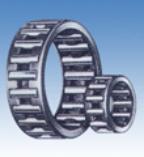
| KBK Piston pin supporting needle and retainer assembly(small end bearing) |
|
|
|
| Piston pin supporting needle and retainer assembly transmit the engine poser through the piston pin.To reduce the impact and |
| lower the noise, the inner diameter of the retainer is often close to the piston pin which means inner guiding method is used. |
| The retainer of piston pin supporting needle retainer assembly is generally made of 20 steel . The small end bearing retainer of |
| high torque force and high speed. is always made of 15CrMo steel. |
|
|
|
|
|
|
|
|
|
|
|
|
|
|
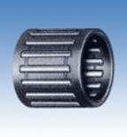
| KZK Crank pin supporting needle and retainer assembly(big end bearing) |
|
|
|
| The crank is driven by the big end of the connecting rod.Therefore,the outer diameter of the retainer should be as close as pos- |
| sible to the inner diameter of the big end of the connecting rod so that the impact can be reduced and the noise lowered . That |
| means out guiding method is used. |
|
|
|
|
|
|
|
| The big end of the bearing revolute around the center of the crank shaft and it the same time it rotates itself . When the speed |
| reaches very high(over 8000rpm),the centrifugal force will be very huge and thus extremely big load resulted on the retainer cr- |
| eating very poor conditions.The retainer of the crank pin supporting needle retainer assembly is generally made of suitably heat |
| treated 15DrMo steel , this greatly increase the strength and abrasion resistance . Meanwhile this will ensure the material the |
| same as the piston pin steel so that they have the same heat expansion factor under the same condition . When the working |
| speed exceeds 8000rpm or the temperature is very high,silver coating to the retainer is suggested. |
|
|
|
|
|
|
|
|
|
|
|
|
| Applicable materials |
|
|
|
|
|
|
|
|
| It is suggested that 15CrMo be used for connecting rod material.After carbonization quenching and tempering , its toughness |
| is increased . The tray surface hardness of the apertures of both small and big ends are no less than HV700 with effective ha- |
| rdened layer no less than 0.5mm.the surfaces of seat holes and the pin tray must be ground very precisely till its surface rou- |
| ghness doesn't exceed Ra0.2. the circularity,cylindricity will be controlled within 0.003mm.the parallelism of the two ends:for |
| high speed 0.02/100.For general purpose 0.03/100. For low speed,0.04/100. |
|
|
|
|
| If the above mentioned precision can not be reached , it is suggested to widen the radical combination gap . Or damage will |
| happen on the bearing due to the abnormal load resulted from over heat. |
|
|
|
|
|
|
|
|
|
|
|
|
|
|
| BIG END GUIDANCE AND SMALL END GUIDANCE |
|
|
|
|
|
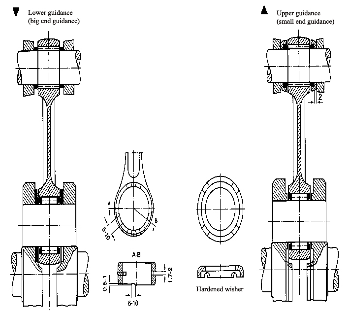
| Big end guidance(lower guidance)and small end guidance(upper guidance)are constituted as shown in Fig 1.Big end guidance |
| is more commonly used . Lower end guidance is considered only in case of very high speed or the overheat resulted from big |
| end guidance. |
|
|
|
|
|
|
|
|
| Big end (lower guidance): |
|
|
|
|
|
|
|
| The big end of the connecting rod and the needle bearings are mounted between the two cranks.So when big end guidance is |
| used,the oil film lubrication among the crank,connecting rod big end and the bearings must be noticed.On the big ends of the |
| connecting rod,the end surfaces are always made into slit, hole or groove shapes so that the lubricating oil can enter the ne- |
| edle bearing smoothly and normal lubrication oil circulation can be maintained. |
|
|
|
|
| The width of the big end needle bearing is the same as the connecting big end.To ensure the effective guidance to the big end |
| bearings and to prevent the connecting from slanting, two washers made of phosphorus bronze are added by the two sides of |
| the big end and a gap of 0.2~0.5mm between cranks are ensured. |
|
|
|
|
| Big end (upper guidance) |
|
|
|
|
|
|
|
| The small end of the connecting rod and the needle bearings are mounted between the piston and the pin and are guided by |
| piston body.To reduce the axle gap,two hardened washers are added onto the end surface of the small end bearings to limit |
| the axial movement of the connecting small end. |
|
|
|
|
|
|
|
 |
|
|
|
|
|
|
|
|
|
|
|
|
|
|
|
|
|
|
|
|
|
|
|
|
|
|
|
|
|
|
|
|
|
|
|
|
|
Fiqure 1 |
| Radical gap |
|
|
|
|
|
|
|
|
| The radical gap should be selected as per the engine type and the operational conditions. The speed, load, lubrication, temp- |
| erature, the material and machining precision of the engine must be specially noticed. The selection of smaller gap can be |
| used to increase the efficiency of the engine but all the parts must be guaranteed by the matched precision. Or the bearing |
| might be burnt. Suitable radical gap should take experience and the test values. |
|
|
|
|
|
|
|
|
|
|
|
|
|
| Recommended radical gap |
|
|
|
|
|
|
|
| Small end: |
|
0.002 - 0.012mm |
|
|
|
|
|
|
| Double stroke big end: |
0.015 - 0.030mm |
|
|
|
|
|
|
| 4 stroke: |
|
0.007 - 0.024mm (for high speed, 20-35% can be increased) |
|
|
|